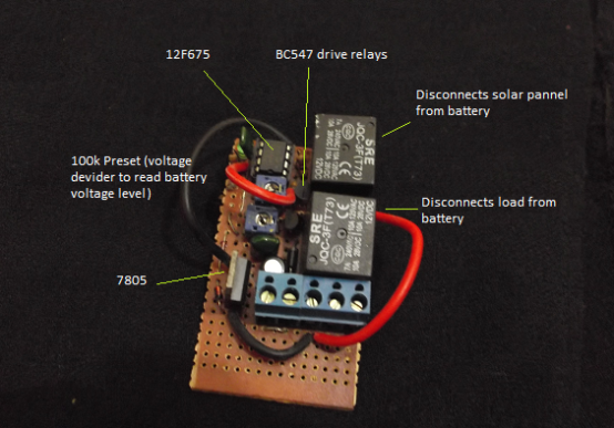
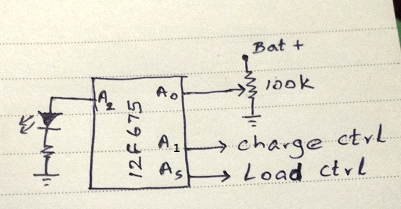
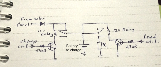
This circuit was build to control charging/discharging of a solar powered battery. A 12F675 monitors the battery voltage through an ADC channel and connects/disconnects solar panel and the load to avoid over charging and over discharging the battery.
An LED connected to the micro controller indicates the state of the battery. When the battery is fully charged (>13v) it blinks in long pulses (2s) and the solar panel is disconnected. When the battery is charging i.e. 12.3v to 13v short pulses about 200ms in each 2s. When the voltage drops below 12.3v the load is disconnected from the battery and LED is blinked two 25ms pulses in each 2s interval.
But there is an issue with this circuit. When the load is connected while the battery is charged to say 12.5v, battery voltage suddenly drops below 12.3v due to current demand from the load and the internal resistance. Open circuit voltage of a battery is not what you get while running. When the load is disconnected, voltage goes back to the original value. This causes the circuit to take false decision and disconnect the load, then voltage restores and the load is connected back… endless loop. This can be avoided if we can detect when the load (say home lighting system) is taking current. A current sense resistor can be used for this. At that time program should use somewhat lower voltage to determine the ‘low battery’ state.
Note that the solar panel is connected through a normally closed relay pins and the load connected through normally open pins.
Program (HiTec-C)

#include <htc.h>
#include <pic.h>

__CONFIG(UNPROTECT & WDTDIS & BORDIS & MCLRDIS & PWRTDIS & WDTDIS & INTIO);

#define _XTAL_FREQ 4000000

void init()
{
    TRISIO = 0b00000001;
    CMCON = 0b00000111; // Comparator Off
    ADCON0 = 0b10000001; // Ref = Vdd, Chan = 0, AD = On
    ANSEL = 0b01010001; // FOSC/16
    __delay_us(30); // Acquisition Delay Min 20 uSec
}

int read_adc()
{
    unsigned int n;
    GODONE = 1; // Start conversion
    while(GODONE); // wait for done
    n = (unsigned int)ADRESH << 8 | ADRESL;
    return n;
}

void delay_ms(int n)
{
    while (n-- > 0)
        __delay_ms(1);
}

void FlashLED(int delay, int count)
{
    while (count-- > 0)
    {
        GPIO2 = 1;
        delay_ms(delay);
        GPIO2 = 0;
        delay_ms(delay);
    }
}

void main(void)
{
    init();

    GPIO1 = 0;
    GPIO5 = 0;

    FlashLED(1000, 1);

    while (1)
    {
        unsigned int t;
        int bCharging;
        int bReady;

        t = read_adc();

        // Note: adjust following magic numbers according to your setup.

        // Battery Level High
        if (t > 900)
        {
            GPIO5 = 1; // stop charging
            bCharging = 0;
        }
        else if (t < 860)
        {
            GPIO5 = 0; // charging
            bCharging = 1;
        }

        // Battery Level Low
        if (t < 750)
        {
            bReady = 0; // battery is discharged a lot
            GPIO1 = 0; // disconnect the load
            delay_ms(30000);
        }
        else if (t > 770)
        {
            GPIO1 = 1; // battery ready for working
            bReady = 1;
        }

        if (bCharging == 0) // > 13v
            FlashLED(2000, 1);
        else if (bReady == 1) // > 12.3v
            FlashLED(200, 1);
        else if (bReady == 0) // < 12.3v
            FlashLED(25, 2);

        delay_ms(2000);
    }
}


Nice circuit, Thank you for sharring. please advice how can i change the cut off chrge voltage to max 14.4v? and load cutt off to 11v?
Good to here you like this. Actually that is experimental.
1. Disconnect the solar panel and give 14.4v to the terminal named Bat+.
2. Change the 100k preset such that ADC pin receives about 4v.You should never touch the preset after this
3. Now the hard part. You have to check what read_adc() returns. You can use a debugger, or by blinking the led if the value is larger than a value you guess. With trial and error you can find the value.
4. Substitute that value (say n) for 900 in the program. That is the fully charged state.
5. Replace 860 with n-40.
6. Give 11v to Bat+ and find what read_adc returns. Replace 750 with that value (say m).
7. Replace 770 with m+20
8. Done.
Hope this helps.
Thank you for your comment, can i put instead two mosfets, Pchanel instead of the Relays?
as it is experimental, did this code tested even in proteus?
Regards,
I don’t think MC can output the voltages required to directly drive p-mosfets specially as they are working attached to the upper voltage rail 14v. You may use a mosfet driving stage in between them like this
I have not used proteus but the trial and error method explained above. A pic simulator alone cannot do this. You need an ICD. I’m not sure this pic supports in circuit debugging 😦
Thank you sir for sharing this great helpfull tutorial. Sir i have a SMPS of 15V for charging 12V lead acid battery. Can you please guide me how to monitor whether my device is working on smps or battery. My purpose is to display that whether equipment is running on mains or battery and also monitoring low battery voltage.
Using a 15v smps is not good for charging a 12v battery. You should use a battery charger to avoid overcharging the battery. If the mains is down you should stop the battery feeding the smps. I.e. Current flow from battery to smps. This can be achieved by using a diode in series with smps. Then just connect a bulb to the smps output. If the bulb is glowing you are running on mains. To monitor low battery state you have to use a voltage comparator circuit.
Thanks sir for your quick reply. Sir I have already done my hardware portion for battery charging, I have used 1N5402 diode and a 12V/10W small bulb to limit current while charging. When battery is discharged lamp glows with maximum brightness and as the battery is charging its brightness keeps on decreasing and when it gets fully charged then lamps gets switched off. Sir I wanted to know that how can i implement this circuit with my micro-controller to detect whether the device is running on battery mode or charging mode.
First you have to sense SMPS output and battery output. Use two 100k presets as i have I have used in A0 pin. Then read their ADC values and decide at what level you should turn on indicators. Finding the correct ADC value is by trial and error. You should make sure that not more than 5v is given to micro controller pins.
Thanks a lot sir, will do as per your guidance.
Wao…! Thanks a lot for sharing your knowledge. Please can this circuit modifies to charge 12V/ 200AH Deep cycle battery through power supply source (instead of solar panels) and also, the load would not be required. Jus only to charge battery and cut off when it is fully charged.
Yes. A simpler circuit can be designed to charge the battery. But some hard coded values depends on your battery characteristics.
I got error when compling the code. error “GODONE”
Please send me the hex file via email
Please check https://forum.allaboutcircuits.com/threads/undefined-identifier-godone.49933/
For the compilation error.
“Defining _LEGACY_HEADERS before including the htc.h file results in the old names working”
My hex file will not work in your circuit as it depends on the 100k preset value. You should adjust 900,860,750 and 770 values in the code to suit your 100k preset value and to suit the characteristics of your battery. To get this circuit working definitely you need some tuning with trial and error.
:0A0000008316FF2390008301562BA6
:1006AC0083019A2B9F149F18592B1E08A300A2019B
:1006BC0083161E088312A2042308A1002208A0009E
:1006CC000800FF308312A007031CA103A11B080024
:1006DC00F930A2006400A20B702B742B6400672B02
:1006EC0001308316850007308312990081309F00FA
:1006FC00513083169F0009308312A000A00B842B6D
:10070C00872B0800FF30A507031CA603A61B0800B7
:10071C00051595236723051195236723882B24083A
:10072C00A1002308A00008007623E830831285106E
:10073C008512A3000330A400A501A50AA6018823F5
:10074C0058232108AC002008AB0003302C02853064
:10075C0003192B02031CB52B8516A701BF2B0330E5
:10076C002C025C3003192B020318C02B8512A70135
:10077C00A70AA80102302C02EE3003192B02031831
:10078C00D02B3030A901AA018510A0007530A10032
:10079C006723DB2B03302C02033003192B02031CC1
:1007AC00DB2B8514A901A90AAA0128082704031D1B
:1007BC00E42BD030A3000730A400EB2B29032A0430
:1007CC00031DEE2BC830A300A401A501A50AF72B2D
:1007DC002A082904031DF92B1930A3000230A401A7
:1007EC00A500A6018823D030A0000730A100672304
:0207FC00A62B2A
:02400E00E2319D
:00000001FF